It is hard to convey how much Khushal has impressed me. His unique blend of pitching skill, technical ability, and strong articulation constantly made me reconsider what’s possible. His sharp insight, strong community contributions, and excellent technical support set him apart from seasoned peers.
Khushal stands out for turning complex problems into simple solutions. When a server crashed late at night, he fixed it solo in hours. He’s raised funds from scratch and constantly inspires the team.
His determination, intellect, and impact are unmatched.
About Me
Hey! I’m Khushal, a tech and AI enthusiast passionate about entrepreneurship and the web. I’m building Worksta for Singapore’s F&B scene, having raised $80,000! I love organizing events and hackathons, engaging 4,500+ students across India. I also work as an engineer at Entropy, tackling climate change by converting wasted data center heat into clean energy. I thrive on crafting impactful solutions for real-world problems that merge innovation, community, and sustainability.
Bad design files will throw errors and create models that explode or cannot be solved, here are some tips
for
importing FOLD or SVG files that work.
Importing FOLD:
The FOLD file format is specified in these
docs.
This tool imports FOLD v1.0 files with all of the following fields populated:
vertices_coords
edges_vertices
edges_assignment
faces_vertices
You may specify the target fold angle of each crease using the edges_foldAngle field.
Note that fold angle is a number in degrees lying in the range [−180, 180].
The fold angle is positive for valley folds, negative for mountain folds, and zero for flat regions.
Accordingly, the sign of edges_foldAngle should match edges_assignment if both are specified.
You may also assign a null fold angle to a crease so that it is allowed to move freely - this is especially
useful when the fold angle is unknown or the crease pattern is fully constrained and able to be driven by
other creases in the system.
If you are unsure whether your FOLD file is valid, you can inspect it using the
FOLD Viewer.
If you are having trouble, please refer to the FOLD spec.
Importing SVG:
The SVG importer supports path, line, rect, polygon, and polyline objects with the appropriate
stroke color:
Mountain folds have red stroke - rgb(255, 0, 0), hex #ff0000
Valley folds have blue stroke - rgb(0, 0, 255), hex #0000ff
Boundary edges have black stroke - rgb(0, 0, 0), hex #000000 - use
this edge type for both the outline of the pattern, and any internal holes.
The final fold angle of a mountain or valley fold is set by its opacity. For example, 1.0 = 180°
(fully folded), 0.5 = 90°, 0 = 0° (flat). Any fold angle between 0° and 180° may be used.
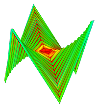
The following
patterns contain creases with varying final fold angles:
Before the model can enter the simulator, this tool will automatically triangulate regions in the
pattern that form polygons with more than three sides.
To control the triangulations, draw lines in yellow - rgb(255, 255, 0), hex
#ffff00. In general, patterns are more stable when their triangulation is symmetric and minimizes long,
skinny triangles. You can see
how the app automatically triangulated your pattern by enabling "Facet Crease" visibility in the
Advanced Options > Edges Visibility
menu on the left side of the screen. It may not be necessary to add triangulation lines on your pattern.
Facet creases (yellow triangulation lines) are creases that try to remain flat (0° fold angle) as
the pattern folds, but some compliance
in the constraints of the simulation will allow them to bend slightly. Drawing in facet creases allows you
to control
the way the model bends in between mountain/valley folds. This is especially relevant in patterns with
curved creases.
If you import an svg with bezier curves and select the checkbox "crease pattern contains curves" in the
import dialog, we attempt to triangulate it for you using the algorithm described by Simple Simulation of Curved Folds Based on Ruling-aware Triangulation.
We recommend trying this first, and add additional facet creases to your svg design where needed.
Cuts have green stroke - rgb(0, 255, 0), hex #00ff00 - use this edge type
to form thin slits in the pattern.
Undriven creases have magenta stroke - rgb(255, 0, 255), hex #ff00ff -
creases of this type will swing freely. Use this crease type when you're not sure what angle some of the
creases in your pattern should fold to.
Line style and stroke width do not matter.
Remove clipping masks from your file before importing.
This tool should be able to automatically clean files of slightly misaligned vertices, stray vertices,
duplicate lines, and extra vertices falling in the middle of an edge,
but it is recommended to remove these errors yourself in order to avoid problems.
If your simulation is not working, check that the imported pattern looks correct by clicking on the
Pattern view in the top nav bar.
You can also download a copy of the imported pattern ( File > Save Pattern as SVG ) and view it in
a vector
editing program of your choice.
For Adobe Illustrator users:
I use Illustrator to create SVGs (though any vector editing program should be fine). Here are some tips I've
found for making svgs to import into this tool.
If you are starting with a pre-made vector file, first release all clipping masks (Select all +
Object > Clipping Mask > Release).
Create geometry using the Line Segment, Rectangle, and Polygon tools.
Illustrator can help you select all lines of a particular type so that you can edit their color or
opacity together. Click the line,
then go to Select > Same > Appearance to select all similar lines in the pattern.
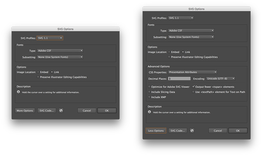
Be sure that CSS Properties is set to Presentation Attributes in the Advanced options.
Finally hit Save As and select .svg extension. I'm using the default SVG 1.1 settings, but
version 1.0 will work as well.
EXPORT OBJ
These OBJs are compatible with Freeform Origami
Filename: .obj
Scale:
Dimensions: ( the OBJ file format is unitless, but typically assumed to be either in inches or mm
)
Dimensions: For more information about the FOLD file format, see the offical docs.
Use the FOLD viewer
to check that your file has been exported correctly.
IMPORT FOLD
SIMULATION ERROR
Average vertex error gives a sense of how much the distance constraints in the
origami pattern are being violated (i.e. how much the sheet is being stretched). The error at each vertex is
evaluated by averaging the
percent deviation of all its distance constraints with adjacent vertices. This error is
reported as a percent of the total length of the distance constraint to remove scaling effects.
This measurement is equivalent to
Cauchy strain or engineering strain of the distance constraints on this system.
Increasing the Axial Stiffness will tighten these constraints and
lower the error in the simulation.
To visualize the error of each vertex graphically, select Strain Visualization under Mesh
Material
in the left menu.
SIMULATION SETTINGS
This app uses a compliant dynamic simulation method to solve for the geometry of an origami pattern
at a given fold angle. The simulation sets up several types of constraints: distance constraints prevent the
sheet from stretching or compressing, face constraints prevent the sheet from shearing, and angular constraints
fold or flatten the sheet. Each of these constraints is weighted by a stiffness - the stiffer the
constraint, the better it is enforced
in the simulation.
Axial Stiffness is the stiffness of the distance constraints. Increasing axial
stiffness will decrease the stretching/compression (strain) in the simulation, but it will also slow down
the solver.
Face Stiffness is the stiffness of the face constraints, which help the axial constraints prevent
deformation of the sheet's surface between the creases.
Fold and facet stiffnesses correspond to two types of angular constraints. Fold Stiffness is the
stiffness of the mountain
and valley creases in the origami pattern. Facet Stiffness is the stiffness of the triangulated faces
between
creases in the pattern. Increasing facet stiffness causes the faces between creases to stay very flat as the
origami is folded.
As facet stiffness becomes very high, this simulation approaches a
rigid origami simulation, and models the behavior of a rigid material (such as metal) when
folded.
Internally, constraint stiffnesses are scaled by the length of the edge associated with that constraint to
determine its geometric stiffness. For Axial constaints, stiffness is
divided by length and for angular constraints, stiffness is multiplied by length.
Since this is a dynamic simulation, vertices of the origami move with some notion of acceleration and
velocity. In order to
keep the system stable and help it converge to a static solution,
damping is applied to slow the motion of the vertices. The Damping slider allows you to control
the amount of damping
present in the simulation. Decreasing damping makes the simulation more "springy".
It may be useful to temporarily turn down damping to help the simulation more quickly converge towards its
static solution - especially
for patterns that take a long time to curl.
A Numerical Integration technique is used to integrate acceleration into velocity and position for
each time step of the simulation.
Different integration techniques have different associated computational cost, error, and stability. This
app allows you to choose
between two different integration techniques: Euler Integration
is the simplest type of numerical integration (first order) with large associated error, and
Verlet Integration is a
second order integration technique
with lower error and better stability than Euler.
COMPLIANT DYNAMIC SIMULATION
....
COMPLIANT STATIC SIMULATION
....
RIGID STATIC SIMULATION
....
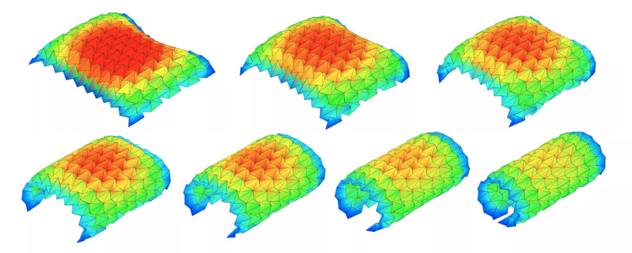
STRAIN VISUALIZATION
Cauchy strain or engineering strain is a unitless measurement of how much a material is being
stretched or compressed under load.
The Strain Visualization illustrates the strain across an origami sheet by mapping it to a color from
blue (no strain) to red (max strain).
USER INTERACTION
Toggle this control to enable/disable mouse interaction with the origami model. When enabled,
mousing over the model will display a highlighter; clicking and dragging allows you to
interact with the model in real time. Very vigorous interactions with the model may cause it
to pop into a strange configuration that it can't escape - use the Reset button to start
the simulation again from a flat state.
ROTATION SPEED
Speed :
( radians per frame )
BACKGROUND COLOR
Color (rgb hex) : Hex colors are 6 digit alphanumeric codes that specify different colors. You can get
these codes using a color
picker.
SVG IMPORT SETTINGS
Vertex merge tolerance (px) :
Vertices within this px tolerance in the SVG will be merged into one. It is recommended to
keep this number above zero.
For curved folding
Check this box if the crease pattern contains curves.
Intervals of vertices for discretization (px) :
Curves and borderlines are divided into segments by this value. It is recommended to
keep this number above zero.
Approximation tolerance of curves (px) :
Curves are approximated by polylines. The smaller the value, the higher the quality of
the approximation.
This app uses GPU functions that are not supported by this device/browser,
please try again on desktop with Chrome/Firefox.
Scale:
Increasing scale allows you to record at higher than screen
resolution.
Dimensions: Resize browser window to change aspect ratio.
Quality ( 0-63 ):
Framerate ( 1-60 fps ):
Framerate ( 1-60 fps ):
Num simulation steps per frame:
Notes: This feature captures the output of the canvas only - no UI or cursor
will be included. Do not resize window while recording. You can increase the
amount of motion per frame by increasing the "Num simulation steps per frame". Check the View
menu (above) for more rendering options.